Thursday, January 26, 2012

Hide And Seek

I have been asked to make a device that allow a space capsule to be found at sea after splashdown. The device should transmit it's GPS position via. VHF radio to a fleet of recovery vessels.
The device should allow regular people without special equipment or training to receive the GPS position.
It was suggested to use plain speech to transmit a WGS84 GPS message that is compatible with most navigation equipment.

This is my initial approach to solving this problem.
First the numbers 0 to 9 and the words "East", "West", "North" and "South" was recorded using a digital recording program (Audacity). The audio file was cleaned and compressed so that the words had an equal voloume and the length was fitted to exactly 32 kSamples. The audio file was then converted to 8bit mono@8kHz .raw format. The start sample and duration of each word was noted.
A special program was made that would transmit the .raw file over a serial port. A 24C256 IIC EEPROM was connected to an Arduino board and a firmware was made to receive the .raw file and flash it into the 24C256.
The EEPROM now contained spoken words that could make up the WGS84 message and a list of starting points and durations for each word.
The firmware in the Arduino board (later to be replaced with custom hardware) was changed to a firmware that received GPS data in the form of NMEA and read these out using the words from the EEPROM.
The micro controller on the Arduino board outputs the audio as PWM which is low pass filtered to make a analog line signal. This signal will later be fed to a custom VHF transmitter that will be integrated as part of the system.

This is a audio test of the system so far. The voice is synthesized but will be replaced by a sexy female voice.

The GPS and audio chip

Sunday, January 22, 2012

Active control of payload direction

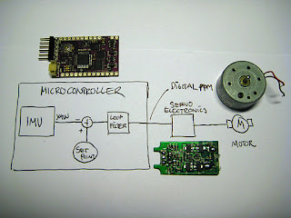
By changing the set-point of the payload stabilizer the direction of the payload can be actively controlled. This could be useful for panning on-board cameras etc.
In this experiment set point was commanded to sweep between +90 and - 90 degrees with the following profile:
Red=yaw(roll), green=command, 20mS/div.

In the video the payload section vibrates a bit. This is a result of the loop-filter not being properly re-tuned after the motor driver was changed.

More payload stabilizer

After playing a bit with the stabilizer i got annoyed with the motor controller I had used. It was the circuit board from an old analog servo. It regulated the motor with 50Hz PWM, had a limited output range and an annoying dead-band. All this led to noisy regulation and oscillation caused by the dead-band.
1st. set-up

The micro controller has the capability to output the motor command as a 8kHz PWM- and a direction signal. Using these signals to drive a simple MOSFET H-bridge i was able to get a much smoother and quieter regulation.

2nd. Driver.

Thursday, January 19, 2012

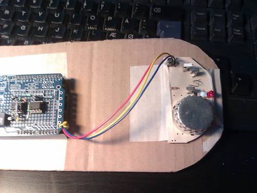
Payload roll-stabilizer for spinning rocket

Rather than trying to roll stabilize a rocket it is sometimes desirable to let the rocket rotate around its length axis and then counter-rotate the payload section.
This device is a quick'n dirty prototype to explore this.


Wednesday, January 18, 2012

New IMU


I am now using the ArduIMU V3 for my flying/guidance experiments. The AHRS firmware for this device has not yet been released but I have managed to get some preliminary firmware together.
The performance of this device seem promising but I have encountered some electrical problems. It is extremely sensitive to noise when powered on external 5V power supply. It can not be powered by the same 5V bus as e.g. servos. It does however have its own on-board voltage regulator that works well when supplied directly from a higher voltage.
There will be much more about this IMU on this blog.

RCTP V2 build pictures


Monday, January 16, 2012

By popular demand...

Drawings for the RCTP (.hpgl)
You may need to adapt a bit for the servos you use.
Here is how I calculate servo positions from pitch, roll, and yaw.
Mind that the RCTP MKII is yet untested and may not fly at all.
Just for people to play with, sorry I can not support this.

Friday, January 13, 2012

RCTP Mk II parts

Made some new parts today for an updated test platform. The new device has with slightly larger control surfaces and some of the more annoying mounting issues has (hopefully) been resolved.

Wednesday, January 11, 2012

RCTP 1. tethered test

Since only a small test space was available the RCTP was teathered. Most of the time the teather was slack and thus not affecting the flight.

Tuesday, January 10, 2012

Videos of tuning process

Here is a video of parts of the tuning process.


More RCTP tuning goodness

After the unfortunate propeller-meeting-flesh-incident i have decided that the RCTP needs to be tuned without touching it.

 Adding a gimbal around it's center of gravity let me tune pitch and roll individually.
All data are in and the RCTP should now be stable on all axes.
Pitch response
AND NO BLOOD!!!


I'm singing in the lair..

I was asked if it would be possible to make a device that react to singing. Initially I thought "sure, but it will require a powerfull computer, some signal processing software and complicated algorithms etc".
Somehow I couldn't shake the thought that there may be a simple way to do it.
A while ago i made a decoder for some DominoEX radio communication signals. It was a small microcontroller that took an audio signal from a radio receiver and decomposed it into its frequency components, analyzed these and turned them into data. The frequency range of this signal coincidentally corresponds to that of the human voice.

I thought that there may be a way to use part of this system to look for tones of singing. This was the idea.


I made this quick'n dirty prototype using a AVR microcontroller...
...and then surpriced everybody by singing loudly. The graph show the score*100. I think with some tweaking  it will be possible to make a simple micro controller device that detects singing.

Pitch and roll tuning end in pain...

After the initial success i went on to tuning the PID controllers for pitch and yaw. After 20 fairly sucessfull minutes i accidently hit the throttle while holding on to the elastic ribbon and WHACK ... the rotor cut deeply into two of my fingers sending blood everywhere.
Bad times. Experiment now suspended until i have all my digits back...

Moments of robot tuning

After completeing the RCTP hardware the flight controller needed to be adjusted for stability. I am using a simple PID controller for now.
Starting with YAW I suspended the RCTP from an elastic ribbon so that it was able to yaw freely.
Throttle and YAW tuning parameters was supplied from the RC-controller via wirerless. Measurement data was received via. cable.

I chose some conservative initial settings for the PID controller (Blue: Integral=0, Green: Proportional=30, Yellow: Derivative=35-ish). And commanded (via the RC controller) a yaw angle of 0.
When starting the rotor the system was oscillating around the YAW axis as suspected. Increasing the D-term (again via. a slider on the RC controller) cancelled the oscillation. A push on the RCTP confirmed that the regulation loop worked.

After some testing it was confirmed that the YAW angle of the RCTP was not zero (zero angle is currently the compass angle in which the flight contrroller is power up). Increasing the I-term fixed that problem.
Yaw is now stable regardless of the rotor speed.

Tuesday, January 3, 2012

RCTP roll cage and progress


After a stupid accident I decided to protect the propeller of the Reaction Control Test Platform.
Using 1mm. carbon rods I made a cage that surrounds the propeller. The cage only add 4,9 gram to the structure but is still very strong should easily keep stuff out of the blades.
Total weight now 295,4 gram.
After completing a preliminary firmware for the device I have now flown it a couple of times.
As expected it has a tendency to wobble. This is caused by the gyroscopic force of the propeller. I have designed the firmware so that i can offset the angle between the IMU  thrust vectoring vanes. This should allow me to compensate for these forces.
Right now the flight controller is loaded with a conservative set of control parameters but still seems fairly stable. Over the next couple of days i will be optimizing the system and have more flight testing.

Firmware

Hardware

Geiger counter from recycled stuff


When fiddling around with smoke alarms containing radioactive isotopes I got interested in measuring radioactivity in general. A friend gave me a FZH76V Geiger-Müller tube that require 500V exitation voltage. Most discarded LCD monitor has a high voltage driver for the backlight VFD tubes. Normally these drivers run on 12V and produces a couple of kV but when run on 5V they easily provide the around 500V that a typical GM tube require.
The above circuit can be connected directly to a micro controller and the pulses it generates can easily be picked up on a normal I/O pin.
I have only tested the circuit with the FZH76V tube but i'm sure that it can be adapted to other devices. I know from experience that the exitation voltage need to be within 10% of the specified value for the device for things to work well.

Monday, January 2, 2012

Hacked smoke detector

Hacked smoke detector by geekphysical


Hacked smoke detector, a photo by geekphysical on Flickr.
Hacked this smoke detector to give analog output. This way the ambient smoke level in a room can be monitored.
As most smoke dectors it is based on the MC145017 integrated detector chip. This chip and similar has an amplified analog output from the ionization chamber on pin 14.
The smoke detector can be powered with 5 volt but the build alarm will be on at all times (not a problem if you remove the horn).
The electronics on the Arduino shield are left overs from another project. Only GND, 5V and analog in are needed for this project.
Data out from sensor. Y axis are Arduino A/D values 5V reference. 
Lit the corner of some writing paper at 50cm. distance and briefly wafted the smoke towards the sensor. After a couple of seconds blew on the sensor to clear out residual smoke.

Sunday, January 1, 2012

Reaction Control Test Platform

RTF ~320 g.

~600g of thrust.


Power controller and LiPo battery.

IMU, data logging memory and controller board.


This device allow development of flight routines and control algorithms without the need for actual reaction engines.

New tool in the lair

New tool in the lair by geekphysical
New tool in the lair, a photo by geekphysical on Flickr.

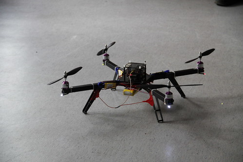
This cool new ArduCopter will be one of the test-beds for my inertial
navigation experiments. Thanks Vanessa!!

New years statement

Well goodmorning everybody. Hope everyone had a good new years evening...
I think this is a good time to make some goals and statements for the year to come.

1) In 2012 i want to work with inertial navigation..

I have long been interested in flying robots and have made a number of experiments involving fixed wing, helicopter, multirotor, balloons and thrust vector controlled crafts.
These all have in common that without control they all perform pretty much like a sack of potatoes.
I find that understanding inertial navigation is the key to success with such projects.
There are a lot of good projects out there, that can be used as a basis, and in 2012 I commit myself to understand and master the art of active guidance.

2) In 2012 I want to improve my skills in rapid prototyping and manufacturing.

Having recently gotten acces to Laser cutting and a variety of CNC facilities, my work have come to depend heavily on these methods.
I commit myself to learning new methods and tools as well as conducting experiments.

3) I want to keep you informed.

I commit myself to record and share my work on this blog and other media.

Happy new year.

Dzl