


Blimp synth building, a set on Flickr.
Sunday, May 5, 2013
Saturday, May 4, 2013
Tiny synthesizer for art project
Was asked to be part of the 2013 click festival. I am part of a workshop called elevated audio. For this we are building tiny remotely controlled audio synthesizers that are carried around the exhibition space by helium balloons.
The challange is to make something that are light enough to keep the balloon size reasonable but still loud enough to be heard.
We decided to use the Arduino synth, that I and Mads Høbye developed some time ago, as a basis but replacing the Arduino board with the much smaller ATTINY85 microcontroller.
Allso we developed code that allowed the ATTINY85 to receive 1200 BAUD serial data provided by an infrared receiver.
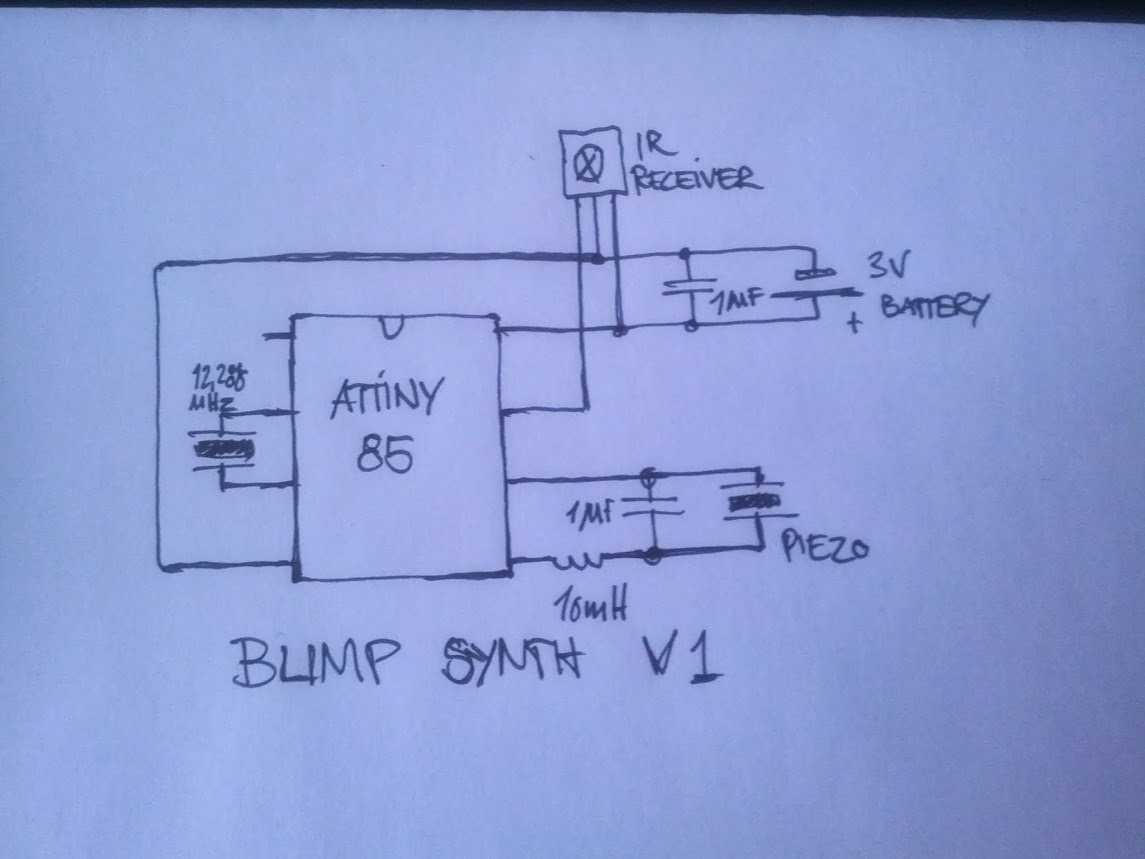
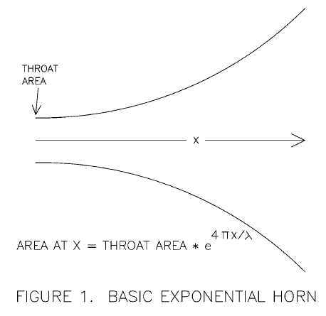
We use piezo transducers to make the sound. These are not very loud on their own so we mount these in a logarithmic horn to amplify the sound. The horns are made from corrugated cardboard to save weight.


The challange is to make something that are light enough to keep the balloon size reasonable but still loud enough to be heard.
We decided to use the Arduino synth, that I and Mads Høbye developed some time ago, as a basis but replacing the Arduino board with the much smaller ATTINY85 microcontroller.
Allso we developed code that allowed the ATTINY85 to receive 1200 BAUD serial data provided by an infrared receiver.
We use piezo transducers to make the sound. These are not very loud on their own so we mount these in a logarithmic horn to amplify the sound. The horns are made from corrugated cardboard to save weight.
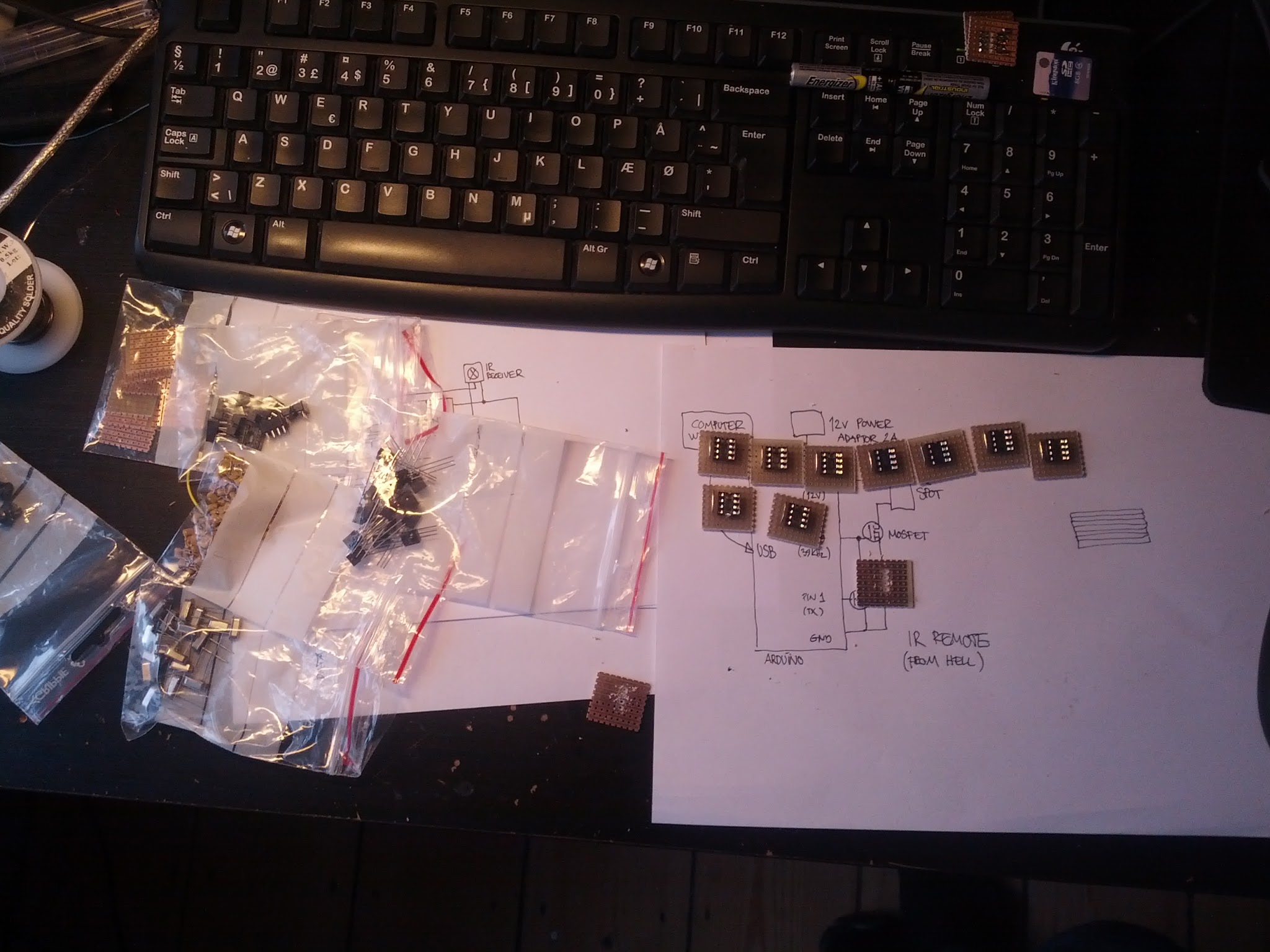
The synth is powered by two AAA batteries. These may not be the most weight sensitive option but they are easy to obtain and replace and we will be using a lot of them since there will be around 20 balloons.
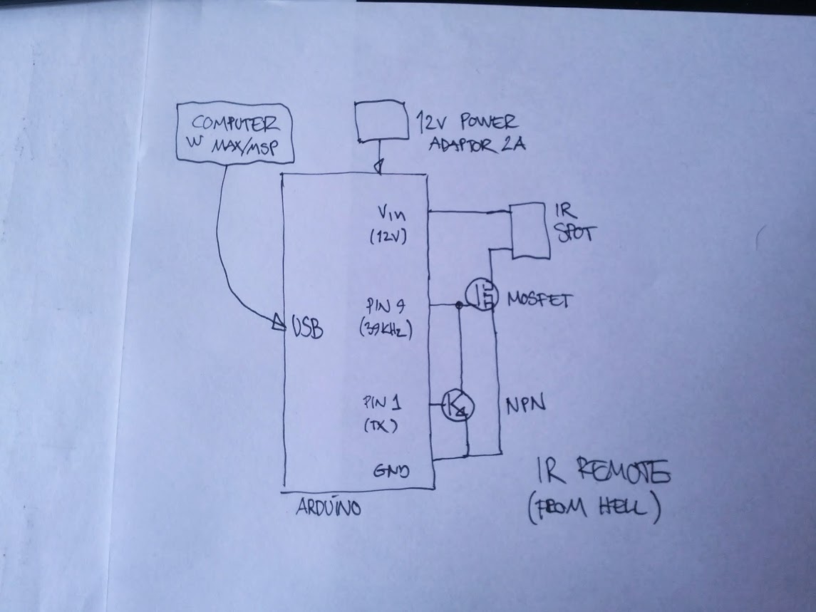
An infrared spotlight is converted into the 'infrared remote from hell' capable of lighting up a whole room with modulated infrared light.
The spot is driven from an arduino board via. a MOSFET driver. The MOSFET gate is connected to a constant 36KHz output from the Arduino. A NPN transistor is used to short out this signal while the TX line is high. When TX goes low the transister opens and the 36KHz signal drives the MOSFET.
A computer running MAX/MSP provides the data to be send to the synths. Each synth has a note_id and can thus be individually controlled.

The synth firmware is still under development but i expect to publish it when it is ready.
Friday, May 3, 2013
Quick and dirty infrared link

In an earlier post I showed how to generate high frequencies with Arduino (or an ATMEGA controller). This trick can be used to make the 40KHz (or similar) modulation used to transmit infrared remote control signals.
By placing a simple infrared diode between pin9 and some other pin on the diode os either off when the pin is high or modulated by the 40KHz signal when it is low.
Very conviently data from the TX (pin 1) or RX (pin0) can be used to drive the LED thus allowing data from either Serial on the microcrontroller or the USB to modulate the signal.
On the receiving side an integrated infrared receiver such as this one convert the modulated light to data.
I have found that with the suggested receiver it is possible to directly transmit serial data at 1200 BAUD.
Here is some Arduino thest code:
//**************************************************************
// Using AVR ATMEGA hardware to generate IR modulation
// Dzl 2013
//**************************************************************
void setFrequency(int d)
{
//Frequency = 16000000/d
TCCR1B&=0xfe; //-Stop generator
TCNT1=0; //-Clear timer
ICR1=d; // |
OCR1A=(d/2); //-+
TCCR1B|=0x01; //-Restart generator
}
void setupFrequencyGen()
{
TCCR1A=0b10000010; //-Set up frequency generator
TCCR1B=0b00011001; //-+
setFrequency(16); //-Start with 1MHz
pinMode(9,OUTPUT); //-Signal generator pin
}
void setup()
{
setupFrequencyGen();
setFrequency(444); //-Make 36KHz
Serial.begin(1200);
}
void loop()
{
Serial.println("Testing the dirty IR link");
delay(1000);
}
Subscribe to:
Posts (Atom)